IInnssttaallllaattiioonn DDaattaa
AAlllleenn--BBrraaddlleeyy
DDaattaa HHiigghhwwaayy//DDaattaa HHiigghhwwaayy PPlluuss
SSttaattiioonn CCoonnnneeccttoorr
(Cat. No. 1770-SC)
TToo tthhee IInnssttaalllleerr
This publication describes the Data Highway Station Connector and the installation
procedures for connecting the station connector to a Data Highway or Data Highway
Plus trunkline cable.
The station connector simplifies Data Highway connections made between the
trunkline and individual droplines, and protects the connections from the industrial
environment. One station connector is required for each dropline. The Station
connector replaces the 1770-XG Data Highway Cable Connector Kit.
WWhhaatt tthhee SSttaattiioonn
CCoonnnneeccttoorr IInncclluuddeess
Each station connector includes the following:
• Junction box with removable cover, and terminal block wired with the following:
- 0.05 mfd 500V DC capacitor (terminals 4 and 5)
- Jumper (terminals 7 and 9)
- Ground wire (terminal 10) and earth ground wire with lug
• Packet containing:
-D-shell cable connector hood
- 15-pin female connector
- Packet of assembly hardware for the cable connector
- Terminator resistor (150ohm, 1/4 watt)
- Shrink tubing
- Cable plug
• A copy of this publication
Be sure each station connector you receive has these parts.
PPuubblliiccaattiioonn 11777700CC--IINN000022AA--EENN--PP —— OOccttoobbeerr 22000066
Supersedes Publication 1770-2.20C — February, 1990
To make reliable connections, you should observe the following wiring
recommendations:
• Use Twinaxial Cable (cat. no. 1770-CD, Belden 9463 or equivalent) for the trunkline
and droplines.
• Be sure to connect the ground wire from the station connector to the earth ground.
• Route the twinaxial cable away from sources of electrical interference.
• Make trunkline connections to the upper side of the station connector; dropline
and earth ground connections to the lower side.
By observing these recommendations and those in the Data Highway Cable Assembly
and Installation Manual (publication 1770-6.2.1), you will reduce electrical noise
interference which can be induced into the trunkline and droplines.
WWiirriinngg
RReeccoommmmeennddaattiioonnss
IInnssttaalllliinngg tthhee
SSttaattiioonn CCoonnnneeccttoorr
Use the following procedures to properly install each station connector. Read the
entire section before performing the procedures.
11..
Cut the dropline cable to your required length.
22
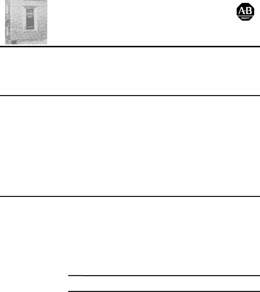
. Prepare the dropline cable for assembly. First carefully remove about one inch of
insulation, foil, braided shield, and filler cord from one end of the cable, freeing
the shield drain wire, clear, and blue insulated wires. Strip about 1/8 inch of
insulation from the ends of the insulated wires.
DDrroopplliinnee
PPrreeppaarraattiioonn
DDaattaa HHiigghhwwaayy//DDaattaa HHiigghhwwaayy PPlluuss
SSttaattiioonn CCoonnnneeccttoorr
DDrroopplliinnee PPrreeppaarraattiioonn
(continued)
33..
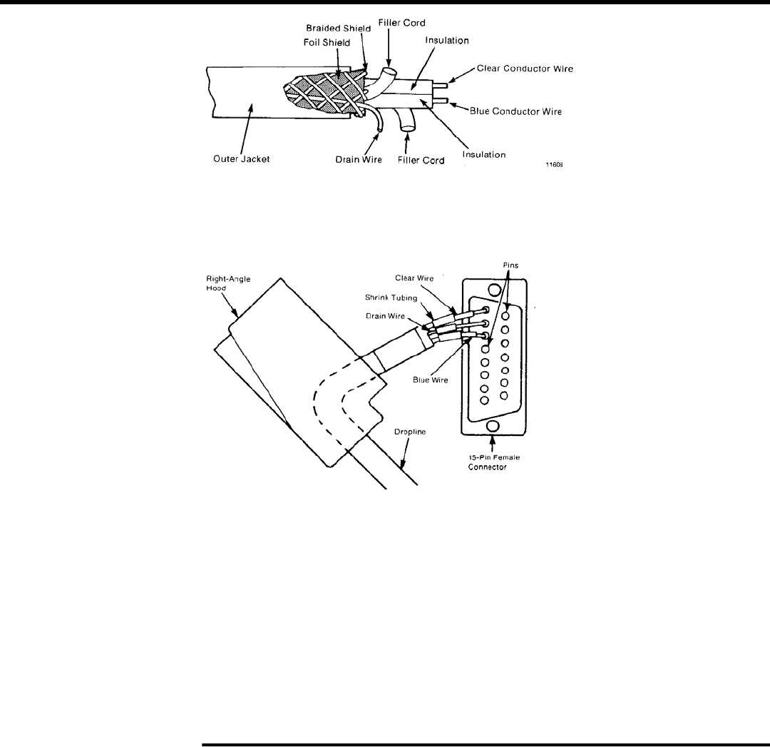
Insert the prepared cable end through the circular hole in the hood of the D-shell
connector. Insert about 1/2 inch of shrink tubing over the ends of the three
conductors.
44..
Solder the blue, clear, and drain wires into their corresponding connector pins in
the back of the 15 pin female connector. Connect the blue wire to pin 6, drain wire
to pin 7, and clear wire to pin 8.
55..
Slide the shrink tubing forward over the soldered connections and shrink the
tubing with a heat gun.
66..
Assemble the 15-pin connector to the D-shell hood.
77..
At the other end of the dropline cable, carefully remove about three inches of
insulation, foil, braided shield, and filler cord, freeing the drain wire, clear and blue
insulated wires. Strip about 1/4 inch of insulation from the ends of the insulated
wires.
11..
Remove the cover and the terminal blocks from the enclosure and mount the
enclosure at the point where you want to add the dropline.
IImmppoorrttaanntt::
Removing the terminal block allows you to make connections to the
screw-clamp terminals more easily.
22..
Cut the trunkline cable. Feed the incoming and outgoing trunkline cable through
their respective cable clamps at the top of the enclosure.
33..
Carefully remove about three inches of cable insulation, foil, braided shield, and
filler cord, freeing the drain wire, clear and blue insulated wires. Strip about 1/4
inch of insulation from the ends of the insulated wires.
TTrruunnkklliinnee PPrreeppaarraattiioonn
DDaattaa HHiigghhwwaayy//DDaattaa HHiigghhwwaayy PPlluuss
SSttaattiioonn CCoonnnneeccttoorr
WWiirriinngg tthhee EEnncclloossuurree
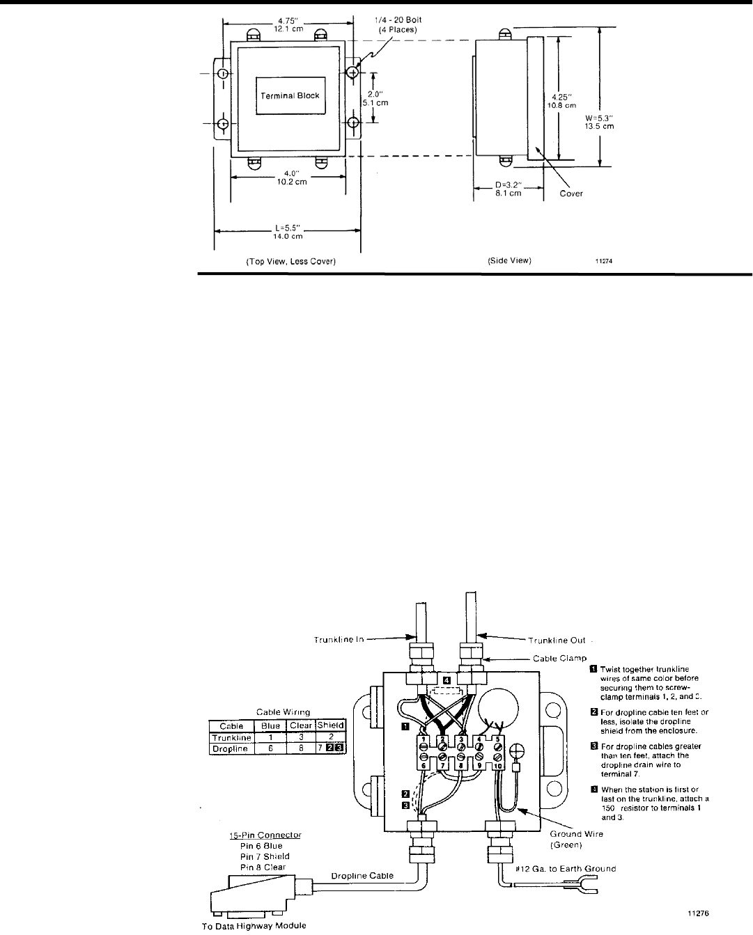
11..
To maintain signal integrity, twist together the same colour wires from each
trunkline cable before securing the wires under their respective screw-clamp
terminals. Connect blue wires to terminal 1, drain wires to terminal 2, and clear
wires to terminal 3 as shown in the wiring diagram.
22..
Feed the free end of the dropline cable through its cable clamp at the bottom of
the enclosure.
33aa..
If your dropline is between 10 and 100 feet, connect the drain wire of your
dropline cable to terminal 7.
33bb..
If your dropline cable is less than ten feet, isolate the shied of the dropline cable
from the enclosure. Tape the drain wire and an protruding shield or foil for
electrical isolation.
44..
Connect dropline cable wires, blue to terminal 6 and clear to terminal 8 as shown
in the wiring diagram.
55..
Secure the trunkline and dropline cables by tightening the cable clamps.

DDaattaa HHiigghhwwaayy//DDaattaa HHiigghhwwaayy PPlluuss
SSttaattiioonn CCoonnnneeccttoorr
TTeerrmmiinnaattiinngg SSttaattiioonnss
This part of the procedure applies only to the first and last station connectors on the
trunkline.
11..
Install the 150 ohm terminator resistor by inserting it into a one inch length of
shrink tubing and connecting the leads to terminals 1 and 3. The trunkline must be
terminated properly with a terminator resistor located in the station connector at
each end of the trunkline.
22..
To maintain the station connector’s NEMA type 13 rating, plug the unused
trunkline cable clamp on the first and last station connectors. Use the cable plug
provided in the packet. Tighten the cable clamp to hold the cable plug in place.
IImmppoorrttaanntt::
The first and last station connectors refer to the physical location along
the trunkline and not to station addresses. Station addresses are independent of
physical locations.
11..
Attach the station connector ground wire to earth ground. The lug accepts a
number of 10 screws.
22..
Mount the terminal block in the enclosure and attach the cover plate. Be sure that
none of the wires are pinched between the cover plate and enclosure.
IImmppoorrttaanntt::
Be careful not to damage the gasket of the cover plate. Gasket damage
could nullify the NEMA type 13 rating of the station connector.
EEnncclloossuurree AAsssseemmbbllyy
For more information on installing a Data Highway or Data Highway Plus cable
installation, refer to the Data Highway Cable Assembly and Installation Manual
(publication 1770-6.2.1).
FFoorr MMoorree
IInnffoorrmmaattiioonn oonn
CCaabbllee IInnssttaallllaattiioonn
• Terminals for trunkline and dropline
OOvveerraallll DDiimmeennssiioonnss ((LL
x
WW
x
DD))
• NEMA type 13 enclosure • 14.0 x 13.5 x 8.1 cm
• 5.5 x 53 x 3.2 inches
SSppeecciiffiiccaattiioonnss
PPuubblliiccaattiioonn 11777700CC--IINN000022AA--EENN--PP,, OOccttoobbeerr 22000066
Supersedes Publication 1770-2.20C-February 1990
